HISTORY
CHAPTER ONE: 1970-1981 The First Decade
CHAPTER ONE: 1970-1981 The First Decade
Introduction
The history of the development of the implantable insulin pump spans decades. Very early in this process scientists realized that delivery of insulin to the peritoneal cavity, rather than intravenous delivery, was the optimal route but their attempts to build a device to achieve this were plagued by the lack of the technological capabilities required to do so. The case can easily be made that the concept and launch of the implantable insulin pump occurred decades before we had the technological capabilities to implement it. The following is the story of the work of the dedicated physicians, scientists and engineers who persisted and worked through the early challenges . Their dedication, throughout a time when so little was known and the needed technology was unavailable, created an opportunity for us today. Today, we now have the technical capabilities to build the ultimate management tool for Type 1 Diabetes.
1970: THE IDEA – THE BEGINNING
In 1970 a brief paper was published in Surgical Forum (A Permanently Implantable Self-Recycling Low Flow Constant Rate Multipurpose Infusion Pump Of Simple Design; Blackshear, Dorman, Blackshear, Varco & Buchwald; Surgical Forum Vol. 21, pp 136-137; 1970).
The paper described a multipurpose, permanently implantable drug infusion pump. In four brief paragraphs the authors who were based in Minneapolis, Minnesota, described the device, its novel energy source for driving fluid (drug) infusion, the initial bench-top studies and their first animal implantation experiments of infusing the anticoagulant drug, heparin. They hypothesized that their device would be useful for heparin delivery, artificial pancreas insulin delivery, organ specific chemotherapy, antihyperlipidemic drug treatment and vasodilatation. Over the next ten years several implantable pump manufacturers would emerge, and in a remarkable one-year period, beginning in 1980, four different research groups would implant insulin pumps into diabetic patients.
1972: THE FIRST DESIGN
The Minnesota group’s implantable pump concept described in 1970 was followed by a 1972 paper (The Design And Initial Testing Of An Implantable Infusion Pump; Blackshear, Dorman, Blackshear Jr., Varco & Buchwald; Surgery, Gynecology and Obstetrics Vol. 134, pp51-56 (January 1972).
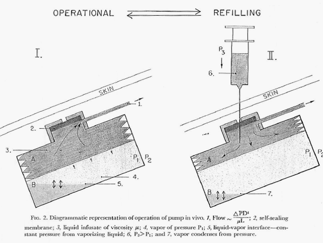
This paper described, in greater detail, the design of the pump, the concept of using the vapor pressure of an isolated fluid as the energy source for delivering the chosen drug, and the results of experimental implantations of the device in animals. The pump was functionally limited to delivering a chosen drug at a single, constant rate which was dictated by the vapor pressure of the fluid in the pressure chamber, the viscosity of the drug solution and the total resistance to flow of the fluid path. Figures 1 and 2 directly below describe the pump and its operation.
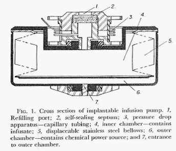
Figures 1 and 2 are from: Surgery, Gynecology and Obstetrics Vol. 134, pp51-56 (January 1972)
1975: AN IMPROVED DESIGN AND EXPERIMENTAL TESTING
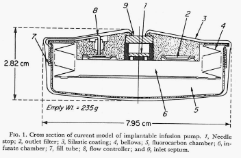
Development continued and in 1975 the Minnesota group published a paper describing a newly designed pump and results of its long-term (one year) implantation delivering the anticoagulant drug, heparin, in experimental animals (One Year of Continuous Heparinization In The Dog Using A Totally Implantable Infusion Pump; Blackshear, Rhode, Varco & Buchwald; Surgery, Gynecology and Obstetrics Vol. 141, pp 176-186; August 1975).
The figure below shows the design of this version of the pump (figure is from the authors 1975 paper cited here).
In this report the authors explain that the constant flow rate previously described actually varied between 8 and 13 percent. Note: Metal Bellows Corporation of Sharron, Massachusetts is mentioned in this paper as providing support for the research. The author’s final words in this paper regarding usages for the device include “….continuous or modulated insulin infusion in the treatment of diabetes.”
1978: EXPERIMENTAL INSULIN DELIVERY BY IMPLANTABLE PUMP
The Minnesota group reports the use of their implantable pump for delivering insulin in a 1978 paper (Design and Initial Testing of a Totally Implantable Transcutaneously Controllable Insulin Delivery Device; Perkins, Dorman, Rhode, Blackshear, Blackshear Jr., Varco & Buchwald; Transactions of the American Society for Artificial Internal Organs (24): 229-231 (1978)).
This was the first report of an implantable device delivering insulin in experimental animals. Insulin was delivered intravenously via the inferior vena cava and therefore the insulin passed directly to the heart from there to the lungs then back to the heart and on to the peripheral arterial circulation.
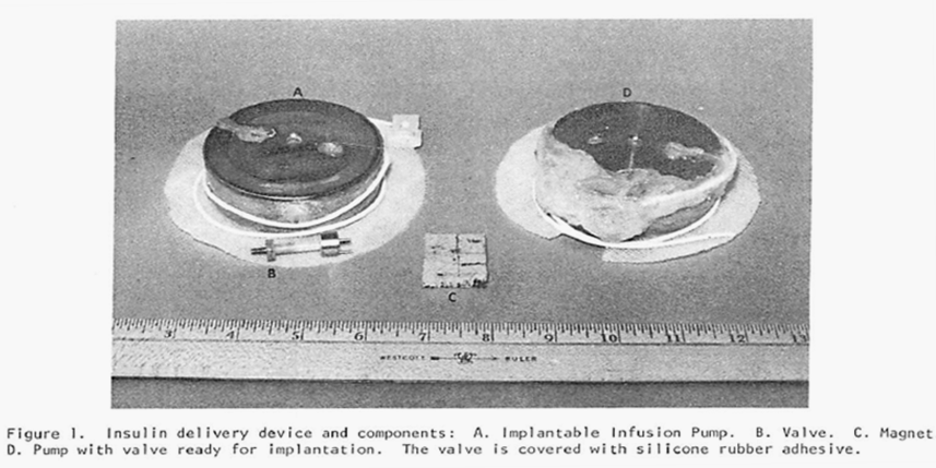
This newest pump also (as did the previous pump) produced a constant flow of the chosen drug but, in addition, it had the capability of switching to one additional, substantially increased rate of flow through the use of a magnet held over the implant site and in proximity to a special valve on the pump. By placing the magnet over the valve, the route taken by the insulin leaving the storage reservoir was considerably shortened (thereby decreasing the resistance to flow by 90% and increasing the amount of fluid allowed to pass in a unit of time). Flow rates were increased by a factor of 15 times over the constant basal flow rate for as long as the magnet was held over the valve. Theoretically a chosen, specific bolus of insulin could be infused by timing how long the magnet was held over the valve. The Figure directly below shows the pump and valve (left image), the magnet (center image) and the pump with the valve attached and covered in silicon prior to implantation. The next Figure graphically illustrates the two possible flow paths – one, high resistance path with the valve inactive and the other lower resistance path with the valve activated by the magnet. Both figures are extracted from the authors 1978 paper cited above.
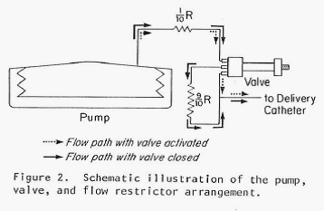
Note: The figure above schematically illustrates the two possible insulin flow paths. Magnetic activation of the valve effectively removes 90% of the flow restriction by bypassing a loop of tubing that represents 90% of the total flow resistance.
1980: A NEW IMPLANTABLE INSULIN PUMP DESIGN
A completely different design for an implantable pump, developed in a cooperative effort between the physician-researchers at the University of New Mexico and Sandia Laboratories of Livermore, California, was reported in 1980 (Some engineering aspects of insulin delivery systems) Spencer, Bair, Carlson, Love, Urenda, Eaton and Schade: Diabetes Care 3, 345-350 (1980).
This pump was designed with the intent of delivering insulin. However, in this early report the authors used a saline solution in their implantation tests (they report difficulty with insulin stability). This pump, quite different in design from the Minnesota pump, used a separate reservoir that sat outside of the main pump containment case and was connected by tubing. Shown in the Figure labeled as 5 (both figures extracted from the original document cited above) .
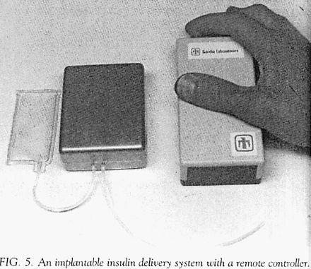
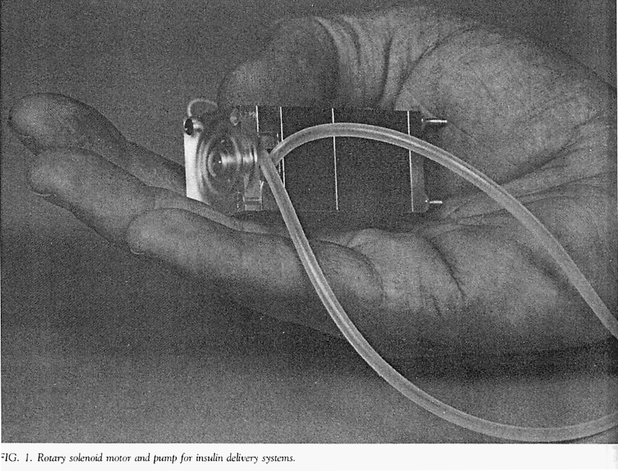
The developers used the same pumping mechanism that they had developed for their earlier external insulin pump. This mechanism was a rotary device that propelled insulin by sequentially compressing a segment of elastic tubing (i.e., a peristaltic process).
The photo below (Listed as figure 1 in their paper) is of the mechanism used to pump insulin in the author’s external insulin pump. The same mechanism was adapted for use in their first implantable pum
